Texture, viewing and shader variations
Goal: Learn how to use texture mapping, to apply projection and viewing, how to work with multiple models in a scene, and try some alternative ways to use shaders.
If you run into problems, you can either look in the textbook, or visit https://registry.khronos.org/vulkan/specs/latest/man/html/. There you will find all the functions and structs and enums used in Vulkan.
1) Procedural texture mapping
Using the results from lab 1, you should now add texture mapping. First of all, we need texture coordinates. These may be stored in the model. Some models, like the bunny you used before, come without texture coordinates. We need a new model, and to make things simple there is a bunny that has texture coordinates in the asset folder for lab 2.
For now, we only need one model. The model file you should use is called "bunnyplus.obj”.
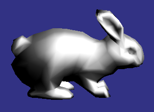
bunnyplus
Why “plus”? Can you see what the difference is to the original “bunny.obj”?
Load the bunny model and draw it. To use its texture coordinates, you need declare the model and pipeline as VERTEX_PNT in the main program.
This will deliver your texture coordinates to a vec2 at location 2 in the vertex shader.
Pass the texture coordinates to an interpolated ("out") variable, and use that (as "in") in the fragment shader to produce some kind of visual effect. Optionally, you can also pass time information to get an animated pattern. There are infinite possibilities here, be creative!
Note, to compile, simply type make lab2-1 in the terminal. This is the same as for lab 1 and will be the same for lab 3 and 4.
Questions:
What kind of procedural texture did you make?
2) Texture mapping
Remember to copy files, including shaders.
Mapping a texture image is slightly trickier because we need to connect it to the descriptor set layout.
First, you need to initialize the descriptor set layout with a vector that contains pairs of uint32_t and VkDescriptorType.
The uint32_t is the binding of the related uniform. This is similar to location for the attributes.
The VkDescriptorType is the type of data we want to use. For this course it will be used for uniforms and textures.
The VkDescriptorType for a texture is VK_DESCRIPTOR_TYPE_COMBINED_IMAGE_SAMPLER.
The VkDescriptorType for a uniform is VK_DESCRIPTOR_TYPE_UNIFORM_BUFFER, but this will only be necessary for lab 3 for TSBK07 and possibly the project.
The initialization for a non-empty descriptor set is defined as following:
initDescriptor(VkDescriptorSetLayout& descriptorSetLayout, VkShaderStageFlags const& shaderStages, std::vector<std::pair<uint32_t, VkDescriptorType>> const& bindings)
The first parameter is the descriptor set layout.
The second parameter is the flag for where we want to use our data. For this course, it should either be VK_SHADER_STAGE_VERTEX_BIT or VK_SHADER_STAGE_FRAGMENT_BIT or both (using the | operator).
The third parameter is the vector containing all the pairs we want to use for the descriptor set layout.
Your goal is to create a binding of an image sampler that is to be used in the fragment shader.
Next, we need a buffer for the texture. It is called AllocatedImage and is similar to the vertex buffers in the previous lab.
To initialize the texture, write the following:
svk.loadTGATexture(texture, "assets/maskros512.tga");
This will load the dandelion from the asset folder and store it in the texture variable which is an AllocatedImage.
Next, to simplify the binding of the descriptor set, as well as the other parts of the model (binding in this scenario refers to the functions that bind the things such as VkCmdBindVertexBuffers) we will use a new container called Object. an Object contains pointers to the following: a pipeline, a pipeline layout, a descriptor set layout, and a model. It also contains a vector of uniform buffers, and a vector of texture buffers.
Declare an Object similar to how you declared the Model:
Object<VertexType> object;
Next, after you've initialized the previous data. You initialize the Object as following:
object.init(&pipeline, &pipelineLayout, &descriptorSetLayout, &model);
To add the texture to this object, you simply type the following:
object.addTexture(binding, &texture);
Where binding refers to the number you used when you added it to the descriptor set layout.
Next, we have 3 functions to simplify our operations in the display loop:
svk.bindObject(VkCommandBuffer buffer, Object<VertexType> object);
svk.drawObject(VkCommandBuffer buffer, Object<VertexType> object;
svk.bindAndDrawObject(VkCommandBuffer buffer, Object<VertexType> object);
bindObject() performs all the vkCmdBindX() functions such as vkCmdBindVertexBuffers(), vkCmdBindIndexbuffer(). It also does vital work for the texture and uniform buffers, so you should always call this if your Object has any of those.
drawObject() calls either vkCmdDraw() or vkCmdDrawIndexed().
bindAndDrawObject() simply calls bindObject() and then drawObject().
That's all you have to do to add a texture to a model.
To access the texture in the fragment shader, you declare the following:
layout(binding = ??) uniform sampler2D tex;
where the binding is the same as what you declared in the main program. Afterwards you can transfer it to vec4 data like this:
outColor = texture(tex, texCoord);
Put a texture on the bunny!
Questions:
How are the textures coordinates mapped on the bunny? Can you see how they vary over the model?
How can you make a texture repeat multiple times over the bunny?
3) Projection
Remember to copy files, including shaders.
So far, we have been limited to a cube world from -1 to 1 in all directions (except for the z-axis unless you're using the extension mentioned in lab 1), and parallel projection. This is not fun, we want a realistic projection. Use this matrix:
#define znear 1.0
#define zfar 30.0
#define right 0.5
#define left -0.5
#define top 0.5
#define bottom -0.5
float projectionMatrix[] = { 2.0f*znear/(right-left), 0.0f, (right+left)/(right-left), 0.0f,
0.0f, 2.0f*znear/(top-bottom), (top+bottom)/(top-bottom), 0.0f,
0.0f, 0.0f, -(zfar + znear)/(zfar - znear), -2*zfar*znear/(zfar - znear),
0.0f, 0.0f, -1.0f, 0.0f };
Also, multiply the y by -1 since the y-axis in Vulkan is inverted (compared to OpenGL and DirectX, ugh):
projectionMatrix[5] *= -1;
Note: To implement the projection matrix in the shader, you can simply extend your push constant to contain two mat4 matrices and make a struct containing two mat4 matrices in the main program.
When you run, the bunny disappears. Why? Add a translation to put the bunny in view.
Time to move to svk_vector_utils!
To make this easy, you can use the svk_vector_utils package. This is a simple vector/matrix package with the bare essentials such as basic C++ operator overloads as well as dot and cross product and matrix multiplication.
To work with matrices, you can do like this:
Declare matrices:
mat4 rot, trans, total;
Set matrices to a rotation and translation (note: these are examples, not your exact transformations!):
trans = T(1, 2, 3);
rot = Ry(a);
Multiply these matrices:
total = trans * rot;
And so on and so forth.
Additionally, there are calls to make a projection matrix in the library. You can use one of the following:
perspective(float const& fovyInDegrees, float const& aspectRatio, float const& znear, float const& zfar);
frustum(float const& left, float const& right, float const& bottom, float const& top, float const& znear, float const& zfar);
If you're using perspective(), a fov of 70 is recommended. You can also get the aspect ratio by calling svk.getAspectRatio().
Important: To make the mat4 transposed in svk_vector_utils, call setAutomaticTranspose(true) in the main() function of the program.
Note: Don't make znear too small.
Questions:
How did you move the bunny to get it in view?
4) Viewing using the lookAt function
Remember to copy files, including shaders.
The task above should give you a useful model-to-world matrix, but for the complete chain you also want a world-to-view matrix, for camera placement. Although it is possible to make one with rotations and translations, it can be better to use a "look-at" matrix as described in the book (section 6.5, page 51 in the 2024 edition).
svk_vector_utils includes two "lookAt" functions, defined like this:
lookAt(vec3 const& position, vec3 const& target, vec3 up);
lookAt(float const& positionX, float const& positionY, float const& positionZ,
float const& targetX, float const& targetY, float const& targetZ,
float const& upX, float const& upY, float const& upZ);
Upload the matrix to the vertex shader and use it as world-to-view matrix. Try placing the camera some distance from origin, looking at origin.
Questions:
Given a certain vector for up, is there some direction you can't look?
5) Diffuse shading
Goal: To render a model with diffuse shading.
Remember to copy files, including shaders.
Finally, we want the bunny to look a bit better, with somewhat realistic light. A good start is diffuse shading.
You need to transform the normal vector in order to make the normal vectors follow the rotation of the model. You do that by removing the translation, which is equivalent to casting the 4x4 matrix to a 3x3 one.
If you have a transformation for your models, it should then be applied to normals as well. Example:
layout(push_constant) uniform constants
{
mat4 modelToWorld;
}
mat3 modelToWorldNoTransform = mat3(modelToWorld);
transformedNormal = modelToWorldNoTransform * inNormal;
That normal vector is now ready to use for light calculations. Use (for now) a hard-coded light source in your shader, like this:
const vec3 light = vec3(0.58, 0.58, 0.58);
You will need to use the following built-in functions in the shaders:
normalize() returns a normalized version of a vector.
dot() takes the dot product.
max() and clamp()... OK, you get the picture?
With 3D models like this, it is more important than ever to use visible surface detection. Try turning Z buffering off. What happens?
Note: Usually, we divide the transformation in three parts: Model to world, world to view, and projection. Normal vectors should only be affected by the first two.
Questions:
Did you implement your light calculations in the vertex or fragment shader? So, which kind of shading did you implement?
Some geometry data must be vec4, others are just as well vec3's. Which ones, and why? How about vertices, light source, normal vectors...?
6) Extra: Gouraud vs Phong
Goal: To evaluate the difference between Gouraud and Phong shading. (Note: This will be more meaningful when we get to specular shading, and more of a curiosity at this point.)
Remember to copy files, including shaders.
In the previous task, you implemented one shader of the two main types (Gouraud and Phong). Now, implement the other one and compare the difference.
Note that for a correct Phong shading, you will make sure you normalize the interpolated normal vectors properly.
Questions:
Was the difference big? If not, why?
You are doing almost the same operations. So what is the difference performance-wise? Compare the two methods from a performance standpoint.
7) Building a scene + camera movement with simplified model loadings
Remember to copy files, including shaders.
Next step is to build a simple scene. It should include at least two different models, and the camera should circle around them.
You will need to create one model-to-world matrix for each model. Use translations and rotations for that.
These matrices should be handled with the same code in your shader, i.e. use the same pipeline for both models. The process can look as following:
1) Update model-to-view matrix for model 1
2) Upload this matrix to model-to-view matrix in shader
3) Bind and draw model 1
4) Update model-to-view matrix for model 2
5) Upload this matrix to model-to-view matrix in shader
6) Bind and draw model 2
Questions:
If you rotate an object or rotate the camera, what matrices are affected, respectively?